Check the whole section before machining
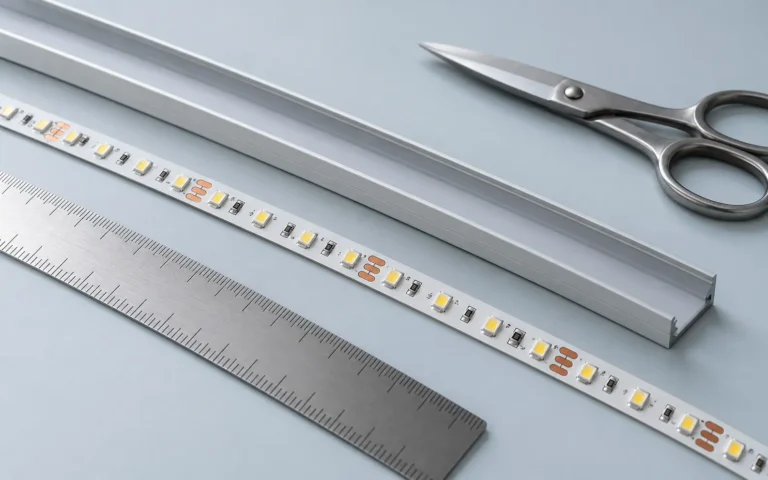
The internal strip space and external channel width are different dimensions. A strip can fit inside the channel while the connector does not. The cover may also need a removal direction that becomes impossible after the shelf is fitted.
| Drawing item | Check before approval |
|---|---|
| Internal base | Strip and connector clearance |
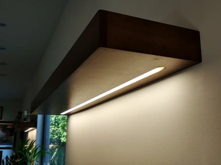
| External body and flange | Groove width, depth and furniture structure |
| Cover | Installation/removal direction and optical choice |
| End caps | Added length and cable exit |
| Fixings | Clip or screw clearance and service access |
Optics and cooling require different evidence
A deeper channel can change the visible source pattern, while the cover changes transmission and distribution. Neither effect is established just by calling a product “opal” or “deep”. Compare the offered parts with the chosen strip.
Aluminium can form part of a heat-transfer path. Performance depends on contact, strip power, profile geometry, mounting and surroundings. Do not treat any small channel as a guarantee of thermal suitability, or claim that a metal profile is mandatory for every strip without its instructions.
A useful order line
Identify the profile reference, cover, finished length, end-cap types, cable exit and fixing set. Add the strip reference and furniture-section revision. If machining or assembly belongs to a different supplier, state that boundary so a bare extrusion is not mistaken for a finished lighting module.
For a floating shelf, ask how a failed strip or damaged cover will be replaced after installation. A neat prototype is incomplete if the service route requires destroying the shelf finish.