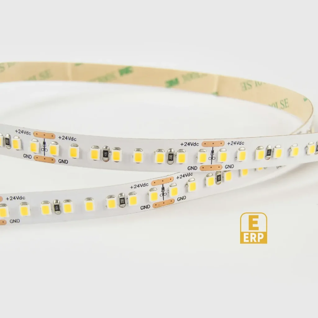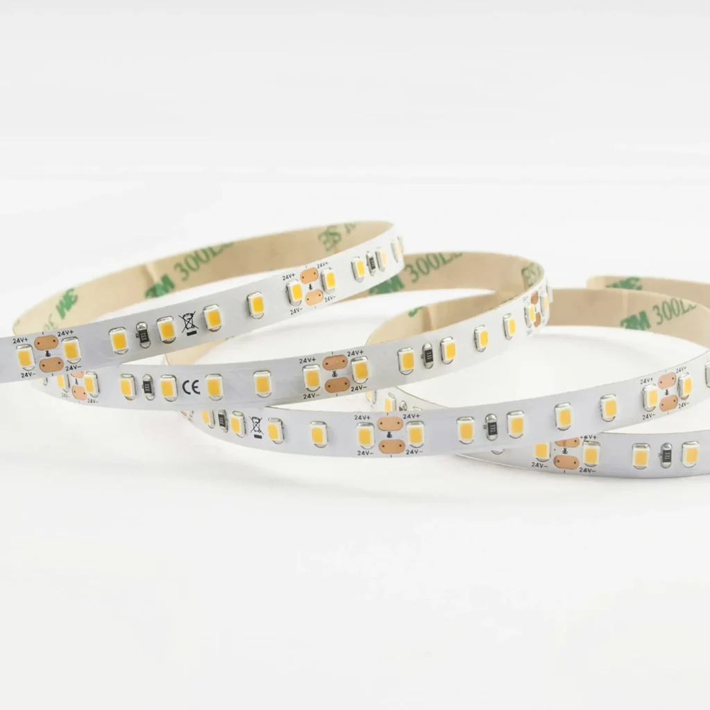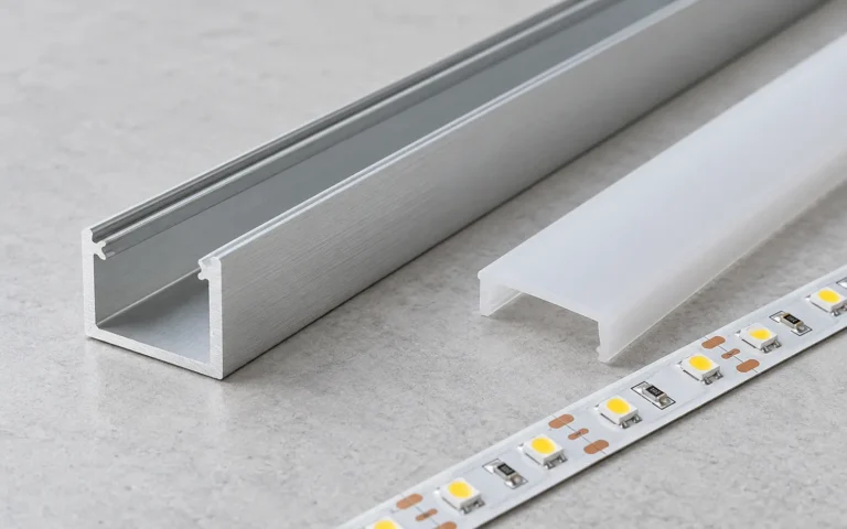

Direct view or reflected view?
Look from the normal standing and seated positions. A source hidden by a cabinet edge may still appear in polished stone or glass. If the unwanted pattern is reflected, moving or shielding the source can be more useful than changing only its construction.
Use the intended surface during the review. Matte board cannot reproduce the specular reflection of a glossy worktop.
Change one part of the optical assembly
| Variable | What to compare | Possible trade-off |
|---|---|---|
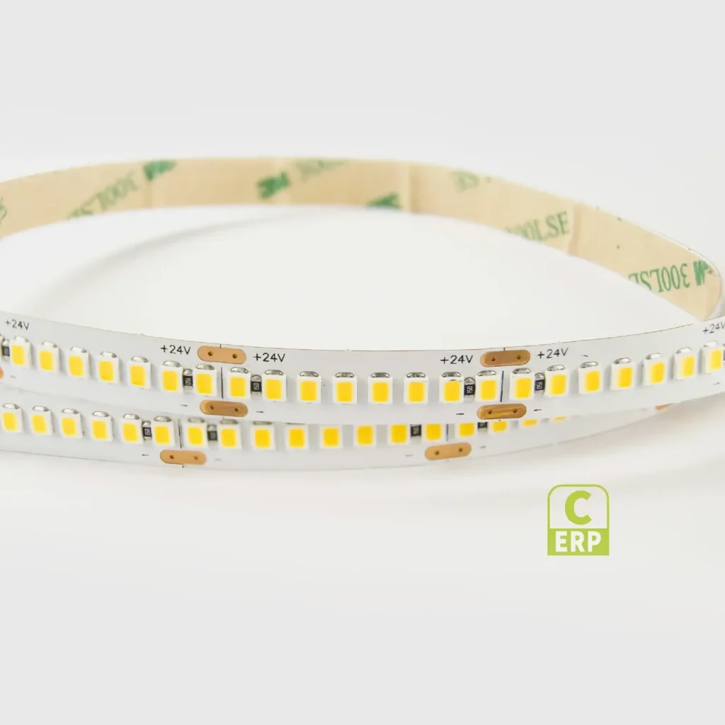
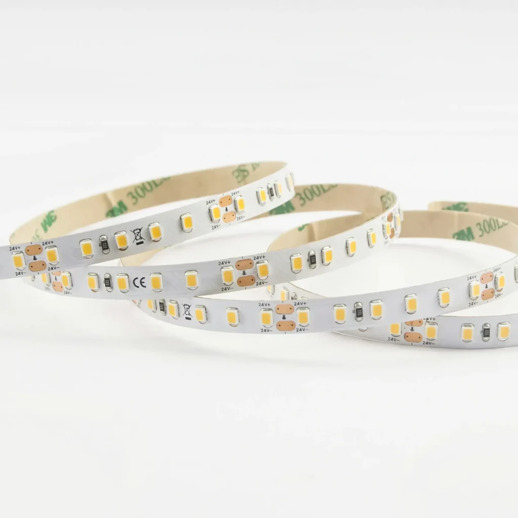
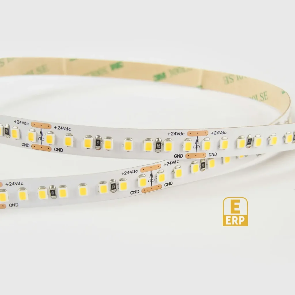
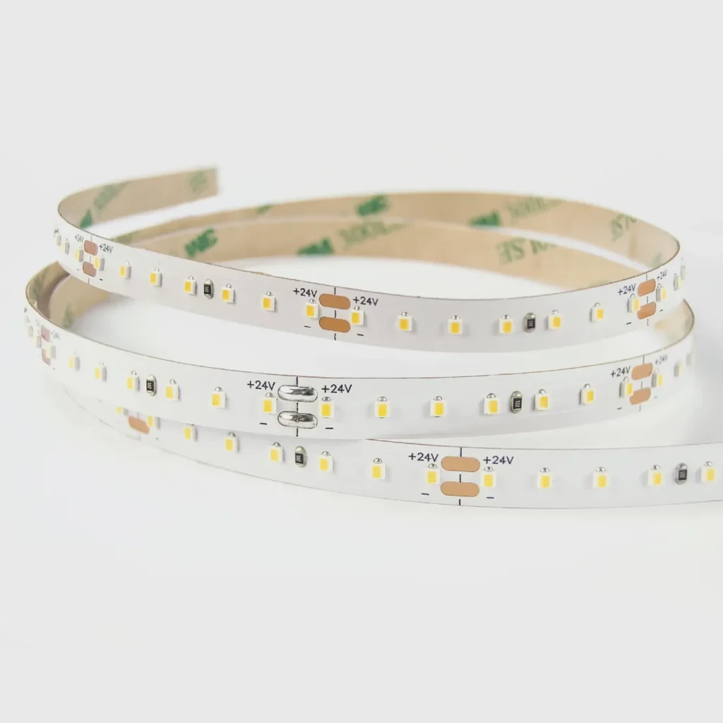
| Strip construction and spacing | The actual lit line in the intended channel | Electrical and dimensional specifications may also change |
| LED-to-cover distance | Shallow and deeper compatible profiles | More recess depth or projection |
| Diffuser | The offered clear, frosted or opal options | Different transmission and distribution |
| Position and shielding | Front/back offset and normal sightlines | Different useful light on the surface |
There is no universal minimum profile depth for every LED pitch and cover. Do not publish one as a design rule without the actual optical evidence.
Define acceptance in the drawing
“Continuous-looking line from the normal seated view with cover C” is more useful than an unqualified “no dots”. Identify any glossy surface that must be included and review the sample there.
Also compare output after selecting the cover. An assembly that hides emitters by substantially reducing useful light may fail the original task. Source smoothness, glare and task illumination need separate decisions.
Will higher density always fix it? No. The full optical detail still matters.
Is any visible reflection a defective strip? Not necessarily. It can be a placement and surface interaction; investigate the complete detail before assigning the cause.